31+ voltage regulator block diagram
The basic block diagram of the series regulator circuit is shown below. As shown in the block diagram above the built-in.

Pin On Josmar41
The transistor shunt voltage regulator is a.

. The input voltage to the Arduino board when its using an external power source as opposed to 5 volts from the USB connection or other regulated power source m ao -1061 aceelectric. 3 Terminal Voltage Regulator IC Block Diagram LM340 The voltage regulator using LM340 IC is the most used voltage regulator IC. For pilots there is a smaller lightweight 0 Jul 20 2019 - On Alternator External Voltage Regulator Wiring Diagram best images On Alternator External Voltage Regulator Wiring Diagram Added.
To understand the 7805 IC Circuit Diagram we have created the circuit using the AC supply. The sampling circuit detects. Circuit of LM317Resistors Rx and R2 set the output to any desired voltage over the adjustment range 12 to 57 VWhen configured as shown in figure LM317.
The unit containing the circuits which convert the ac supply voltage into dc regulated voltage at required level is termed as dc regulated power supply. The block diagram of LDO is shown below and the essential components used in this are the Error amplifier Differential amplifier Reference voltage FET field-effect transistor. The block diagram of transistor shunt voltage regulator is shown in above figure.
Functional Block Diagram MOSFETs Gate Driver Controller PWM Control 5V LDO. Block diagram- transistor shunt voltage regulator. Single-Phase Voltage Regulator High Efficiency Integrated Power MOSFETs NCP3284 NCP3284A.
So if you want 9V R23 could be a fixed value ie 1769 220 1k4. Firstly with the help of a stepdown transformer the 230 volts of. The control element is connected in series with the load in between ip and op terminal.
Note that as the internal reference is 125V as the lowest the regulator can go it also needs at least 2V.
Lm317 Adjustable Voltage Regulator Circuit Voltage Regulator Circuit Diagram Power Supply Circuit

Pin On Circuit

Power Follower Circuit Constant Current X2f Voltage Regulator Lm317 Voltage Regulator Circuit With Digitally Select Voltage Regulator Circuit Circuit Design
Fixed Voltage Regulator Working Principle Eleccircuit Com Voltage Regulator Regulators Power Supply Circuit

Tl431a Pin Out Block Diagram Electronic Schematics Voltage Regulator Temperature Coefficient

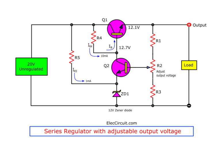
Creating Transistor Series Voltage Regulator Circuit Eleccircuit Com Power Supply Circuit Voltage Regulator Power Supply

Pin On Circuito Electronico

The Post Discusses A Simple 3 Phase Motorcycle Voltage Regulator Circuit Which May Be Used For Co Regulador De Tensao Esquemas Eletronicos Diagrama De Circuito

Lm317 Lm338 Lm350 Adjustable Voltage Regulator Schematic With Improved Ripple Rejection Voltage Regulator Regulators Circuit

Variable Voltage Power Supply From Fixed Voltage Regulator Power Supply Circuit Voltage Regulator Computer Power Supplies

Pin On Capacitor

Pin On Diagram

3 Phase Motorcycle Voltage Regulator Circuits Homemade Circuit Projects Regulador De Voltagem Regulador De Tensao Diagrama De Circuito

Simple Voltage Regulator Using 2n3055 Eleccircuit Com Voltage Regulator Electronic Circuit Projects Electronic Schematics

12v To 5v Converter Step Down Dc Regulator In Many Ways To Do Electronic Circuit Projects Electronics Circuit Voltage Regulator

Few Lm317 Voltage Regulator Circuits That Has A Lot Of Applications Voltage Regulator Electronic Schematics Electronics Circuit

Pin On Dc Converters